
When we left it last month, the basic airframe of the Amp Eater had been completed. The next step was to buy all of the hardware needed to make it fly. I used the excellent website at Robot Birds, http://robotbirds.com/. I bought the following items:
| 1 x Blue Arrow S04314MG heavy duty sub-micro servo 2 x Blue Arrow S04310 standard sub-micro servo 8 x DuBro Micro E/Z Link for 0.032” pushrods Robotbirds Pro 10 amp Brushless ESC V4 Robotbirds 15gm 2300kV brushless outrunner motor Robotbirds DSM2 Compatible 2.4ghz RX – Light weight 25mm light weight indoor wheels 7.4V 25C 330mAh Li-Po GWS 7×3.5 prop TOTAL |
£5.75 £7.00 £2.70 £9.20 £8.95 £8.75 £0.60 £3.25 £1.00 £47.20 |
The good news is that although the initial outlay may seem quite expensive, the only bits that tend to get broken are the depron ones (at £3 per sheet) – indoor flying involves low speeds and light weights, so the energy to be absorbed in crash is relatively low. Consequently all of the above just transplants into a new depron airframe – even the carbon rods can be re-used.
Next come the fiddly bits – fitting it out.
First up was the undercarriage. This is fabricated from two equal lengths of 2mm carbon rod. Some thin piano wire is glued one end of each rod, to make the axles for the wheels. I used cyano for this and then covered the whole joint with electrical heat shrink. Having fed the wire through the light weight wheel, I then put a right angle bend in the wire to retain the wheel. The carbon rods cross through the lower fuselage and then locate in the underside of the opposite wing. You need to reinforce the depron at the cross over point and the anchor points and I used some plasticard (styrene sheet) I had left over from model railway projects. On the prototype, Andy used thin plywood.
The next step is to cut out the holes for the 3 servos prior to gluing them into place with UHU Por. The idea is the get the flight battery to sit exactly on the CG, so if you want to fit a larger battery, it doesn’t upset the balance – always thinking, you see! The correct CG position is 65 mm aft of the wing leading edge and I found that the best place for the elevator and rudder servos was immediately behind the wing trailing edge. The aileron servo was placed on one side of the upper fuselage with a cut out to allow the servo arm to reach through the fuselage.
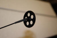
The control horns on the flight controls are fabricated from short lengths of fiberglass strip with a .032” hole drilled at one end. A small slot is cut in the control surface and then the horn glued in with Araldite – it needs to be a really rigid joint and so a 5 minute epoxy is preferable to the ubiquitous UHU Por.
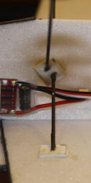
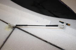
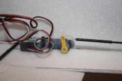
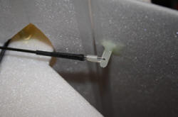
All that remains is to make up the push rods to link the servos to the horns. These are made in the same way as the undercarriage using 2mm carbon rod, .032” piano wire and electrical heat shrink. These are made solid with no adjustment, so you need to be accurate here. Basically, I cut the piano wire to the desired length and then put a right angle bend in to fit through the horn or servo arm. They are retained once completed with the Micro E/Z Links. I then put the piano wire and carbon rod together and slid the heat shrink over them. Heat was applied to hold the piano wire in place in roughly the right place but once I was happy with the final position, I used some super thin cyano wicked under the heat shrink to form the final joint. The accompanying photos show the aileron pushrod, the elevator servo and the rudder horn:
The elevator and rudder pushrods are quite long by necessity and so to make them sufficiently rigid, I fabricated some plasticard fairleads glues to the fuselage side with the pushrod running through them.
There not much left to do now. The motor and ESC were wired together – quite a tricky soldering job as the wires on the motor are quite fine.
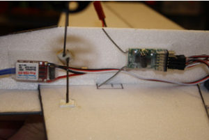
The battery, ESC and receiver are all held onto the fuselage side using sticky backed velco, making sure to respect the correct CG position. The Robotbirds DSM2 receiver took a bit of figuring out as the terminals are not in the usual Ch1 – 6 layout. After a bit of experimentation, I found out what went where. I fly mine with a Spektrum DX6i transmitter and I programmed it for maximum throws on all controls and 60% exponential on ailerons and elevator (+60% in Spektrum terms, -60% in Futaba).
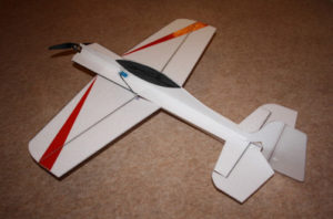
All that was left to do was apply some suitable decoration with Solartrim and she was good to go. My example of the Amp Eater tipped the scales with an AUW of 116g, very slightly heavier than Andy’s prototype, which was under 110g, but with the promise of 235g of thrust from the motor and prop combination, you get the idea of what these shock fliers are all about!!
How did it fly? Well it has big control surfaces, large control movements, weighs naff all and packs a fair few wiggly amps – all of that equals ‘fantastic’. It has transformed the indoor experience for me, it is so agile and you can fly it so slowly that suddenly the Lightning Club sports hall seems twice as big. Anyway, see what you think. Here are two Gilly Tube videos, the first shows Andy Holden’s prototype and the second is my version built from his plan:
http://www.youtube.com/watch?v=6VbfRWCTDGk
http://www.youtube.com/watch?v=H0OGjKmqnmU
I need to thank Andy for all of his help and encouragement during the project. If I’ve inspired anyone to give indoor flying a go, contact Paul Whittle at warton.indoor.flying@gmail.com and come on down.
Gilly