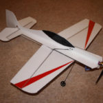
As I’m sure most of you know, I do the indoor flying thing at the Lightning Club in Warton. Up to now, I’ve been content to fly a Blade mSR micro heli and an Eflite Beast biplane. However, most of the lads fly so called shock flyers or ‘shockies’, which are profile models built from depron and carbon. They are extremely light and powerful, allowing them to perform the most outrageous 3D aerobatics within the confines of a sports hall. Furthermore, I’ve learned by hard experience that a scale bipe like my Beast always comes off second best in a mid air with one of these. So I decided that if you can’t beat ‘em, joint ‘em – I’d have to have one too.One of the Lightning Club crew is a chap called Andy Holden, who works in the Eurofighter aerodynamics team at BAE and he designs depron ‘shockies’ just for fun in his spare time. Having had a fly of one of his creations, The Amp Eater, it seemed to fit the bill nicely. Andy even supplied me with a full size plan he’d drawn up on AutoCAD, being the grand chap he is.
The next step was to sort out the materials, principally 3mm depron sheet and the necessary carbon reinforcements. Fortunately, the BAES club had bought in bulk for their members (or anyone else who’s willing to pay for that matter). So, I paid £3.50 for a large sheet of 3mm depron which should be enough to build 2 complete aircraft. I also bought a couple of metres of 2mm carbon rod for the control pushrods and undercarriage, cost £2.50. Finally, I bought 2 metres of 3mm x 0.4mm carbon strip for the airframe reinforcements. Total cost so far £9.60.
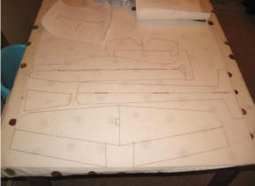
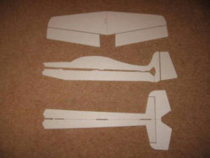
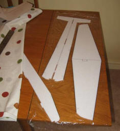
I used the old fashioned pinning through technique to transfer the plan onto the depron sheet (remember building from plans?) although you could easily just cut out the plan to stick on the sheet as a template. Then I carefully used a sharp craft knife to cut out all of the components (without cutting the wife’s nice polka dot tablecloth obviously).
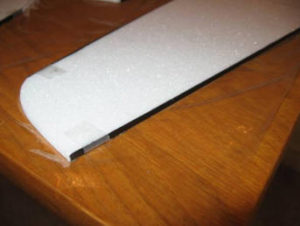
 Depron on it’s own is light but flexible, so to give the structure the requisite rigidity, it is necessary to apply the 3mm x 0.4mm carbon strips. These go along the leading and trailing edges of the wing and along the fuselage sides from the front to the trailing edge of the wing. UHU Por is an excellent adhesive for these applications as when it cures, it still has some residual flexibility, unlike cyano, which dries hard and brittle. The carbon strips were retained using cellotape until the glue dried. It’s critical to keep everything flat while you do this step, so I put down some cling film over the dining room table.
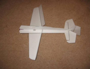
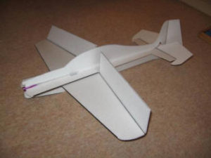
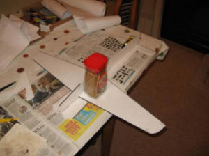
Having left the bits overnight to dry, the next step was to assemble the main airframe components, again using UHU POR. The easiest way to keep everything straight is to lay the horizontal fuselage member on the table and then add the wing and lower fuselage vertical member. Suitable weights were used, as you can see, to keep everything in place whilst the glue dried. Finally, the airframe was turned right side up and the upper fuselage vertical member added. The last bit of depron bashing involved cutting 10mm fillets to add between the horizontal and vertical fuselage members to give a little more rigidity. This was done top and bottom at the front but just on the top of the rear fuselage to leave space for the elevator and rudder pushrods underneath. After this I glued the cylindrical motor mount into the front fuselage, inside the tube created by the fillets.
So far, I’d probably spent a couple of hours on the project but to be honest, it’s more a question of doing a little bit and then going off and doing something else whilst waiting for the glue to dry – the down side of UHU POR.
Next came the mounting all of the flight control surfaces. These are hinged using 3M tape, which is like a plasticized cellotape. The ailerons and elevator leading edges are chamfered at 45° and tape applied to top surface whilst everything is flat on the table. Next the control surfaces are folded back onto the wing / tailplane and the lower hinge tape added. The same hinging technique is quite common on gliders, such as my Dreamflight Weasel, as it guarantees no aerodynamic leakage. The rudder has to be chamfered on both sides but otherwise the technique is the same.